使用 ESP8266 作電機控制(1)驅動風扇
風扇,不就是通個直流或交流電就轉得起來了嗎?是這樣沒錯,筆者也只懂得這樣而已XD,也因此才要學習與筆記的。
電機控制涵蓋的內容範圍是相當深廣的,深廣到不容不懂的筆者在此置喙。因此再次強調只是學習筆記。
以下會先收集沿路看到的參考資料。
參考資料
- 利用 Raspberry Pi 控制 PWM 風扇及轉速偵測
- 涵蓋面向相當廣,內容相當豐富的影片教學網站。Small electronic projects , tutorials, and reviews for sensors, ESP8266, Arduino, Raspberry Pi, and ESP32。
- ESP8266TimerInterrupt
- ESP8266_new_pwm
- 4-Wire fans
- Why and How to Control Fan Speed for Cooling Electronic Equipment
風扇
- 在此要學習的,更細分地說,是散熱風扇,是直流散熱風扇。
- 再細分有有刷,及無刷。
- 無刷就會涉及到幾相,其就須有相位控制驅動,然而散熱風扇本身就是目的元件,因此相位控制驅動的元件,簡稱驅動 IC 就會內建在風扇上面。也就是通常我們使用上無刷風扇並不需要再外掛一顆驅動器。無刷散熱風扇直接通上電源就可以使用了。
- 不管有刷或無刷,馬達是電流驅動元件,因為都有線圈為主體,就會有電感上的物理特性。馬達構造種類也繁多控制方式不一而足。因此讓馬達動起來可能不難,但要每一時刻如所預期地運轉著就涉及到很多技術層面了。
- 直流有刷馬達一般是二線,通電就能用。我們以 5V 全速 3000 轉的直流有刷馬達為例。若要做到轉速調控,只要降低電壓就能做到降轉控制的目的。也可以是三線的,第三線就會是轉速的回饋。一般是由 Hall sensor 來回饋。我們透過供應電壓,轉速回饋,調節電壓,如此反覆地,來做到對風扇的定速控制,稱為閉迴路控制,例如,要定速在 1000 轉,透過此閉迴路控制,得到 1.80007 V 時轉速穩定保持在 1000 轉。但看到了嗎?純類比電路比較難實現電壓的任意微調,故 PWM 因運而生。透過定電壓開關開關地供應,由開關頻率(freq)與佔空比(duty cycle)輸出此定電壓,便可輕易實現 Vrms 的線性調整(但這沒有意義)。要基於成一個系統的觀點下控制才有意義,即,閉迴路系統。開迴路控制的話筆者完全沒認知就只能避開談它了。
- 無刷風扇內建驅動 IC。二線式與三線式的概念與有刷相同如上述。而四線式,即筆者要找來玩來學習的,便是多一腳位做 PWM 輸入。即,Vdd,Gnd,PWM_in,R_out。如下圖筆者淘了一顆來,但沒有它的規格,所以第一步要做的就是讓它轉起來,並量測另外兩根 pin 是否有轉速的回饋訊號。黑(Gnd)綠(Vdd)PWM_in(?)R_out(?)
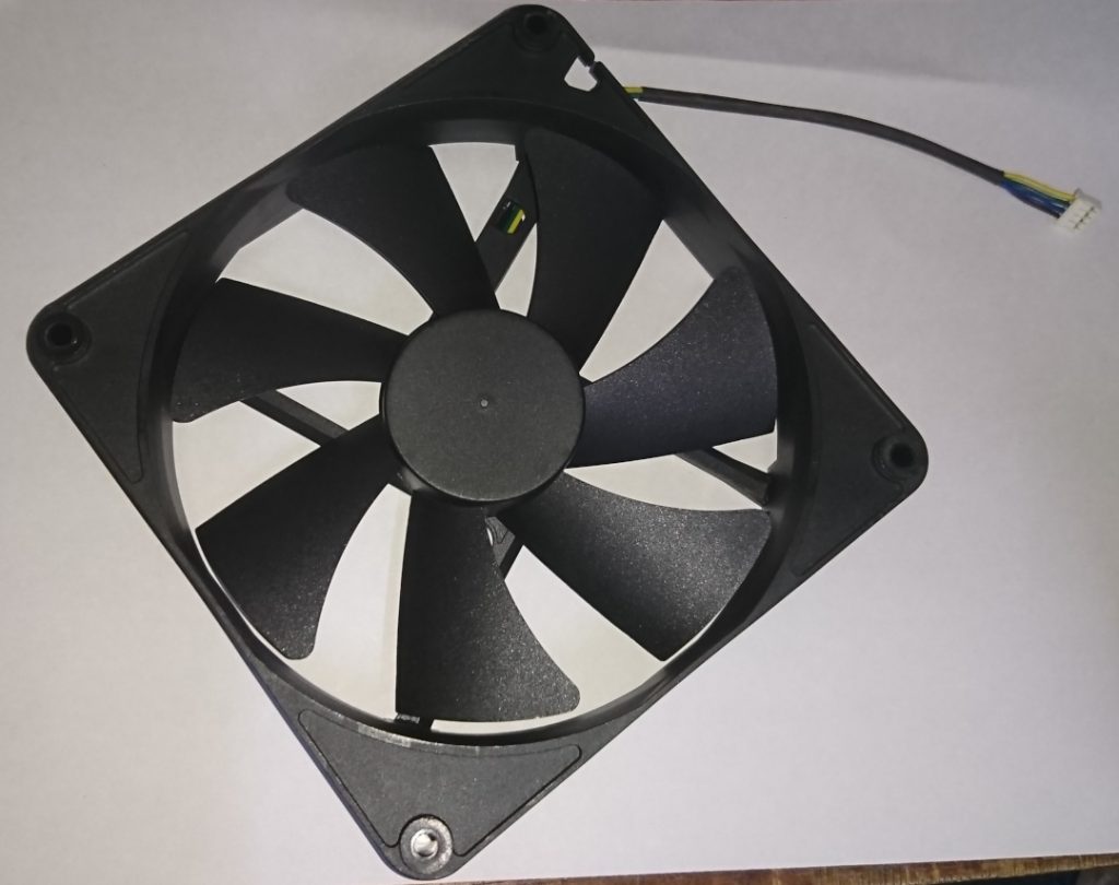
- 結果兩支訊號線都勾不到訊號,只好回去看一下以前的商品頁才驚覺三條線,不,它是四條線,黑-(Gnd)綠+(Vdd)黃Y(R_out)藍P(溫度控制)。所以 PWM 輸入就直接走 Vdd(見續述)。而 R_out 筆者還是量不到訊號包含加了上拉電阻。很有可能是筆者在試正負極時把它燒掉了吧 XD。另外仔細想想藍線溫控,應該就是指 PWM 控制,低電平反驅動。實際將藍線短地確實就不轉了。將電源及 PWM_in 分開有幾個好處,一來供電源穩定也毌須額外的 MOSFET 元件,二來獨立的 PWM 通道可識別小訊號並由單晶片直接控制。再者可直接單單直流驅動或加上 PWM 低電平反驅動控速兩用。
- 主要就是要它的轉速回饋訊號我們才玩得下去。故找來另一顆如下圖。正負極明顯就不用逐線上電嘗試,故這次就抓得到 R_out 訊號了;需加上拉電阻。
ESP8266 v.s. RPMs
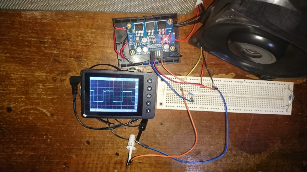
前面文章曾談及 ESP8266 的 GPIO 中斷用法。很直覺地我們可透過一支 GPIO 接到風扇的 R_out 腳位,獲取每次上緣(或每次下緣)觸發的中斷,相隔的時間就是風扇轉動週期。當然也可用 change 觸發更為敏捷,但中斷數更頻繁。
我們接著看若 3000 轉的風扇:3000rpms / 60second = 50revolutions / 1000ms = 1rev / 20ms。即,每 20ms 就會觸發一次中斷,這在獲取風扇轉速時的代價(panality)不低。因此若只基於偵測轉速的考量下,是可以有別的折衷作法的。不過於此我們是要做到風扇定速的閉迴路控制,所以實時地偵測是必要的。再者,若風扇不轉則 GPIO 中斷豈不是不觸發?有問題的做法是轉速低於某值(取兩秒一轉視為合適/30rpms)便直接設為零。然而若高轉風扇突然卡死呢?沒問題的作法是?我們只能在每次計算出轉速後打開或重設定時中斷,例如 2 秒,定時中斷觸發後關掉定時中斷,來處理不轉。至於觸發模式的選用,原則上若不轉是高準位則用上緣,低準位則用下緣則必能在風扇停止那時觸發最後一次。對了,那定時中斷呢?前面文章也談到就使用 Ticker。
驅動風扇的考量
在硬體的能力範圍內,PWM 輸出頻率愈高愈佳因為代表單位時間 Vrms 能夠愈穩定或愈細緻/例如在 1s 下有著高斯曲線的輸出,瞬間輸出愈彈性/例如在 10ms 下輸出三成。但 ESP8266 據說無硬體 PWM,只有軟體模擬函式庫,且筆者尚不懂得去使用,加上至此我們只學達控制 ms 級的精細度,故,不幸地當前筆者只能做到 500Hz 的 PWM。甚著,若要做到 duty cycle 的調整只能再粗分;20 階,PWM 也只能是 50Hz 了。當然這是在不使用 loop() 的前提下。若使用 loop(),精細度約略可達 1s/80MHz=125ns。程式模組化是大前提也是本文如此作法的原因。我們將用定時中斷産生 PWM。GPIO 輸入中斷偵測轉速。
我們立基於使用一顆沒使用過它的直流無刷三線風扇。故會有一個測試函式檢測風扇 duty cycle 的上下界。一旦跑了此函式便會更新預設的上下界。PWM 50Hz,duty cycle 20 階,不在階上階會取 floor()。將使用 WeMos TTGO 板子,轉速便可顯示在顯示器上。
程式碼
#include <ESP8266WiFi.h>
#include <Arduino.h>
#include <U8g2lib.h> // make sure to add U8g2 library and restart Arduino IDE
#include <SPI.h>
#include <Wire.h>
#include <Ticker.h>
/////////////////////// for TickerVerify
int ticker_verify_cnt, ticker_verify_los;
void TickerVerify(){
static int current_time = millis();
int new_time = millis();
int diff=new_time-current_time;
if (diff >= 2){
if (ticker_verify_los<diff) ticker_verify_los=diff;
ticker_verify_cnt++;
}
current_time = new_time;
}
///////////////////////
String str_speed; // for display fan speed
bool Timeout_10s(){
static int current_time = millis();
int new_time = millis();
if (new_time < (current_time + 10000)) return false;
current_time = new_time;
return true;
}
#define MY_FAN_SPD_PIN 0 // GPIO0, for sensing fan speed feedback
#define MY_PWM_OUT_PIN 5 // GPIO5, for PWM output
#define MY_FAN_SPD_TGR FALLING // the edges to trigger regarding to a period
Ticker myTicker_pwm, myTicker_speed; // toggle PWM; measure periods
int fan_period;
int fan_step_cnt_low; // dec counter
int fan_step_cnt_high; // dec counter
int fan_step_reld_low; // current fixeds for reload
int fan_step_reld_high; // current fixeds for reload
int fan_duty_cycle; // steps should be 0 to 20, d-c should be 0 to 100
// 定義 GPIO0 ISR function, for speed sensing
// a period is measured from between recurrent edges
ICACHE_RAM_ATTR void ISR_GPIO0(){
static int current_time = millis();
int new_time = millis();
fan_period = new_time-current_time;
current_time=new_time;
// set 2 seconds for timeout
myTicker_speed.attach(2, [](){myTicker_speed.detach();fan_period=-1;});
}
unsigned Fan_speed(){
if (fan_period<=0) return 0;
return 1000*60/fan_period; // RPM
}
void Fan_setDutyCycle(unsigned dc){ // at 50Hz, 20 steps.
if (dc>100) dc=100;
fan_duty_cycle=dc;
fan_step_reld_high=dc/5;
fan_step_reld_low=20-fan_step_reld_high;
fan_step_cnt_high=fan_step_reld_high;
fan_step_cnt_low=fan_step_reld_low;
}
// 定義 GPIO5 Ticker function, for pwm output at 50Hz, 20 steps. So, still 1ms should go.
void Ticker_GPIO5(){
///myTicker_pwm.attach_ms(1, Ticker_GPIO5);
if (fan_step_cnt_high){
digitalWrite(MY_PWM_OUT_PIN, HIGH);
fan_step_cnt_high--;
}
else if (fan_step_cnt_low){
digitalWrite(MY_PWM_OUT_PIN, LOW);
fan_step_cnt_low--;
}
else if (fan_duty_cycle){ // neither then is time to reload or reset new
// since an intending high or low is action after leaving this function,
// so inside this function sould always "renew" high or low.
// and in this block the state is low.
if (fan_step_reld_high){
fan_step_cnt_high=fan_step_reld_high-1;
digitalWrite(MY_PWM_OUT_PIN, HIGH);
}
else fan_step_cnt_high=fan_step_reld_high;
fan_step_cnt_low=fan_step_reld_low? fan_step_reld_low-1: fan_step_reld_low;
}
/////////////////////// for TickerVerify
TickerVerify();
///////////////////////
}
// it must called before using the fan or used after a fan-stop,
// since duty cycle set 0 can stop fan but pwm func still polled so stop-fan if not uses.
// set duty cycle before starting fan, however reverse might ok.
void Fan_start(){
myTicker_pwm.attach_ms(1, Ticker_GPIO5);
}
void Fan_stop(){
myTicker_pwm.detach();
digitalWrite(MY_PWM_OUT_PIN, LOW);
}
#define OLED_SDA 2
#define OLED_SCL 14
#define OLED_RST 4
U8G2_SSD1306_128X32_UNIVISION_F_SW_I2C u8g2(U8G2_R0, OLED_SCL, OLED_SDA , OLED_RST);
char str1[17]; // scroll this text
byte dir1; // for str1
// a null-terminated string already in an frmsz-size frm-frame with or without leading spaces will be wiggling in it.
// dir stores 0(forward) or 1(backward, non-zero) represents current direction which will be auto reversed.
void TextInFrameWiggle(byte &dir, byte frmsz, char *frm){
for (int i=0, j=0; i<frmsz; i++){
if (frm[i]!=' '){ // find the 1st non-space character incl. 0
if (dir){ // backward
if (i){
do {frm[i-1]=frm[i];} while (frm[i++]);
return;
}
else dir=0;
}
// forward
j=i;
while (frm[j++]);
if (j-i==frmsz) return; // means no-leading-space string occupies entire frame
if (j==frmsz){ // time to turnaround
--i;
dir=1;
continue;
}
do {frm[j]=frm[j-1];} while (--j!=i);
frm[j]=' ';
return;
}
}
}
void setup_u8g2() {
delay(100);
u8g2.begin();
strcpy(str1, "-=*U8g2*=-");
Serial.println("");
Serial.println("U8g2 Ready.");
}
void setup_fan() {
// 宣告成中斷 pin for fan speed measuring
/// pinMode(MY_FAN_SPD_PIN, INPUT_PULLUP); /// 可能需要這一步規劃;待測
attachInterrupt(digitalPinToInterrupt(MY_FAN_SPD_PIN), ISR_GPIO0, MY_FAN_SPD_TGR);
// 將 GPIO5 規劃成 PWM 驅動
pinMode(MY_PWM_OUT_PIN, OUTPUT);
Fan_start();
}
void setup() {
Serial.begin(115200);
setup_u8g2();
setup_fan();
}
int fan_adjust=0;
void loop() {
if (Timeout_10s()){
Fan_setDutyCycle(fan_adjust);
fan_adjust+=7;
if (fan_adjust>100) fan_adjust=0;
}
////Fan_setDutyCycle(100);
u8g2.clearBuffer(); // clear the internal memory
u8g2.setFont(u8g2_font_8x13B_mf); // choose a suitable font
TextInFrameWiggle(dir1, 17, str1);
u8g2.drawStr(0,10,str1); // write something to the internal memory
str_speed=Fan_speed();
u8g2.drawStr(0,28,str_speed.c_str()); // write something to the internal memory
u8g2.sendBuffer(); // transfer internal memory to the display
delay(1);
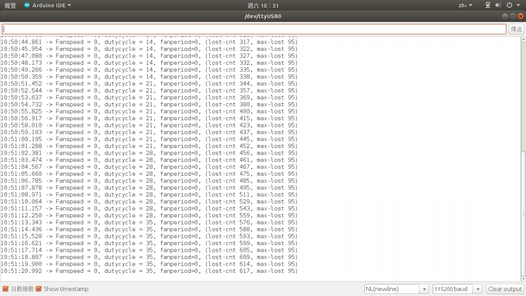
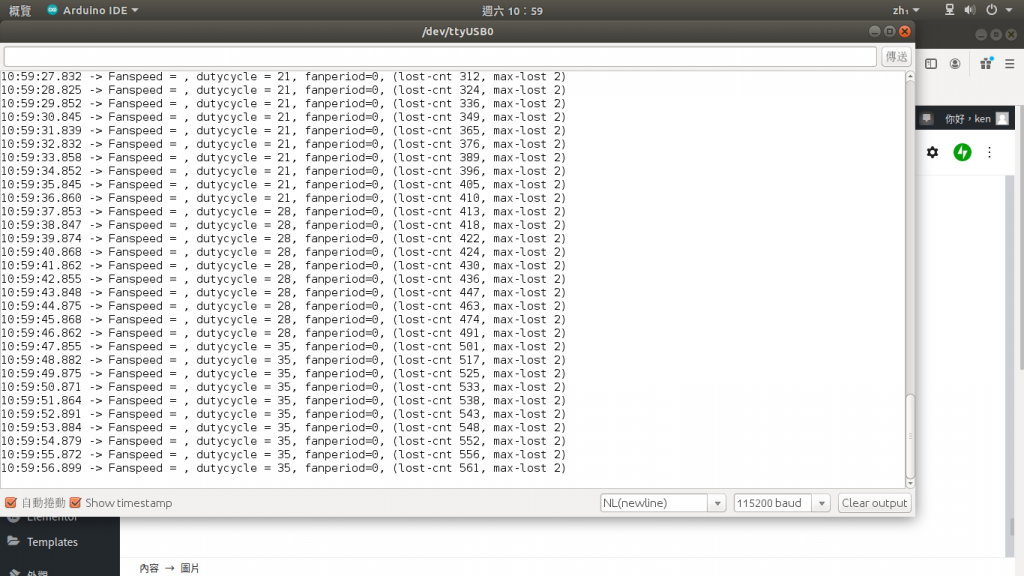
Serial.printf("Fanspeed = %s, dutycycle = %d, fanperiod=%d, (lost-cnt %d, max-lost %d)\r\n",\
str_speed.c_str(), fan_duty_cycle, fan_period, ticker_verify_cnt, ticker_verify_los);
delay(1000);
}
當前結論
- 透過程式碼實測發現可能有一個問題及確定有一個問題
- 在驅動 IC 的控制下,開關 Vdd 可能造成驅動 IC 重設,即,轉速訊號可能不對。
- 因加了開關電晶體,風扇的電源是完全異於接於電腦 USB 的開發板電源的。除非離線至使用風扇電源。因此轉速訊號在開發板接電腦時是無法讀取的/浮動的。
- Ticker 的觸發是會 lost 的或延遲的。但未能定論除非掛示波器來算 pulse 數目。
- 在前面的文章中有提到,官方 SDK 能避用就避用只因怕衝突。但此處既已避用硬體的 timer1,只使用 Ticker,卻只能有 50Hz 的 PWM,實在是圈圈圈。50Hz 對風扇來說實在是太低了。另找尋 Arduino-based 可用的 Timer 或 PWM,發現包裝出來的函式庫仍用上硬體 timer1。不過,ESP8266_new_pwm 這支,請見參考資料連結,似乎是“更直接”使用到 timer1,即所謂的虛擬硬體 PWM。其稱為改寫 SDK 並與 SDK 相容(SDK 是將 pwm 控制直接包成 lib,故沒有程式源碼)。故,筆者的下二步,先驗證使用 Ticker 確實會 lost 或大延遲,將再加入一個 TickerVerify 函式查看最大的延遲或漏失。再來,就是閱讀這份虛擬硬體 PWM 了:在該程式中的這個函式,pwm_intr_handler,將 static 的宣告字拿掉才編譯得過。
- 對了,上面筆者寫的範例,有一個很大的缺點就是在每個時基都要中斷以檢查 count 是否已數完/數完轉態。而如果用上硬體計時中斷/也唯有使用之,才能在任意設定的時達後觸發一次中斷/以轉態。
ESP8266_new_pwm source code
為了方便取用,我將作者的程式碼貼於此處,並可在 D1-mini 上閃燈。
/*
 * Copyright (C) 2016 Stefan Brüns <stefan.bruens@rwth-aachen.de>
 *
 * This program is free software; you can redistribute it and/or modify
 * it under the terms of the GNU General Public License as published by
 * the Free Software Foundation; either version 2 of the License, or
 * (at your option) any later version.
 *
 * This program is distributed in the hope that it will be useful,
 * but WITHOUT ANY WARRANTY; without even the implied warranty of
 * MERCHANTABILITY or FITNESS FOR A PARTICULAR PURPOSE.  See the
 * GNU General Public License for more details.
 *
 * You should have received a copy of the GNU General Public License
 * along with this program; if not, write to the Free Software
 * Foundation, Inc., 51 Franklin St, Fifth Floor, Boston, MA  02110-1301 USA
 */

/* Set the following three defines to your needs */

#ifndef SDK_PWM_PERIOD_COMPAT_MODE
  #define SDK_PWM_PERIOD_COMPAT_MODE 0
#endif
#ifndef PWM_MAX_CHANNELS
  #define PWM_MAX_CHANNELS 8
#endif
#define PWM_DEBUG 1
#define PWM_USE_NMI 1

/* no user servicable parts beyond this point */

#define PWM_MAX_TICKS 0x7fffff
#if SDK_PWM_PERIOD_COMPAT_MODE
#define PWM_PERIOD_TO_TICKS(x) (x * 0.2)
#define PWM_DUTY_TO_TICKS(x) (x * 5)
#define PWM_MAX_DUTY (PWM_MAX_TICKS * 0.2)
#define PWM_MAX_PERIOD (PWM_MAX_TICKS * 5)
#else
#define PWM_PERIOD_TO_TICKS(x) (x)
#define PWM_DUTY_TO_TICKS(x) (x)
#define PWM_MAX_DUTY PWM_MAX_TICKS
#define PWM_MAX_PERIOD PWM_MAX_TICKS
#endif

//#include <c_types.h>
#include <pwm.h>
//#include <eagle_soc.h>
//#include <ets_sys.h>

// from SDK hw_timer.c
#define TIMER1_DIVIDE_BY_16             0x0004
#define TIMER1_ENABLE_TIMER             0x0080

struct pwm_phase {
    uint32_t ticks;    ///< delay until next phase, in 200ns units
    uint16_t on_mask;  ///< GPIO mask to switch on
    uint16_t off_mask; ///< GPIO mask to switch off
};

/* Three sets of PWM phases, the active one, the one used
 * starting with the next cycle, and the one updated
 * by pwm_start. After the update pwm_next_set
 * is set to the last updated set. pwm_current_set is set to
 * pwm_next_set from the interrupt routine during the first
 * pwm phase
 */
typedef struct pwm_phase (pwm_phase_array)[PWM_MAX_CHANNELS + 2];
static pwm_phase_array pwm_phases[3];
static struct {
    struct pwm_phase* next_set;
    struct pwm_phase* current_set;
    uint8_t current_phase;
} pwm_state;

static uint32_t pwm_period;
static uint32_t pwm_period_ticks;
static uint32_t pwm_duty[PWM_MAX_CHANNELS];
static uint16_t gpio_mask[PWM_MAX_CHANNELS];
static uint8_t pwm_channels;

// 3-tuples of MUX_REGISTER, MUX_VALUE and GPIO number
typedef uint32_t (pin_info_type)[3];

struct gpio_regs {
    uint32_t out;         /* 0x60000300 */
    uint32_t out_w1ts;    /* 0x60000304 */
    uint32_t out_w1tc;    /* 0x60000308 */
    uint32_t enable;      /* 0x6000030C */
    uint32_t enable_w1ts; /* 0x60000310 */
    uint32_t enable_w1tc; /* 0x60000314 */
    uint32_t in;          /* 0x60000318 */
    uint32_t status;      /* 0x6000031C */
    uint32_t status_w1ts; /* 0x60000320 */
    uint32_t status_w1tc; /* 0x60000324 */
};
static struct gpio_regs* gpio = (struct gpio_regs*)(0x60000300);

struct timer_regs {
    uint32_t frc1_load;   /* 0x60000600 */
    uint32_t frc1_count;  /* 0x60000604 */
    uint32_t frc1_ctrl;   /* 0x60000608 */
    uint32_t frc1_int;    /* 0x6000060C */
    uint8_t  pad[16];
    uint32_t frc2_load;   /* 0x60000620 */
    uint32_t frc2_count;  /* 0x60000624 */
    uint32_t frc2_ctrl;   /* 0x60000628 */
    uint32_t frc2_int;    /* 0x6000062C */
    uint32_t frc2_alarm;  /* 0x60000630 */
};
static struct timer_regs* timer = (struct timer_regs*)(0x60000600);


ICACHE_RAM_ATTR
////static
void
pwm_intr_handler(void)
{
    if ((pwm_state.current_set[pwm_state.current_phase].off_mask == 0) &&
        (pwm_state.current_set[pwm_state.current_phase].on_mask == 0)) {
        pwm_state.current_set = pwm_state.next_set;
        pwm_state.current_phase = 0;
    }

    do {
        // force write to GPIO registers on each loop
        asm volatile ("" : : : "memory");

        gpio->out_w1ts = (uint32_t)(pwm_state.current_set[pwm_state.current_phase].on_mask);
        gpio->out_w1tc = (uint32_t)(pwm_state.current_set[pwm_state.current_phase].off_mask);

        uint32_t ticks = pwm_state.current_set[pwm_state.current_phase].ticks;

        pwm_state.current_phase++;

        if (ticks) {
            if (ticks >= 16) {
                // constant interrupt overhead
                ticks -= 9;
                timer->frc1_int &= ~FRC1_INT_CLR_MASK;
                WRITE_PERI_REG(&timer->frc1_load, ticks);
                return;
            }

            ticks *= 4;
            do {
                ticks -= 1;
                // stop compiler from optimizing delay loop to noop
                asm volatile ("" : : : "memory");
            } while (ticks > 0);
        }

    } while (1);
}

/**
 * period: initial period (base unit 1us OR 200ns)
 * duty: array of initial duty values, may be NULL, may be freed after pwm_init
 * pwm_channel_num: number of channels to use
 * pin_info_list: array of pin_info
 */
void ICACHE_FLASH_ATTR
pwm_init(uint32_t period, uint32_t *duty, uint32_t pwm_channel_num,
              uint32_t (*pin_info_list)[3])
{
    int i, j, n;

    pwm_channels = pwm_channel_num;
    if (pwm_channels > PWM_MAX_CHANNELS)
        pwm_channels = PWM_MAX_CHANNELS;

    for (i = 0; i < 3; i++) {
        for (j = 0; j < (PWM_MAX_CHANNELS + 2); j++) {
            pwm_phases[i][j].ticks = 0;
            pwm_phases[i][j].on_mask = 0;
            pwm_phases[i][j].off_mask = 0;
        }
    }
    pwm_state.current_set = pwm_state.next_set = 0;
    pwm_state.current_phase = 0;

    uint32_t all = 0;
    // PIN info: MUX-Register, Mux-Setting, PIN-Nr
    for (n = 0; n < pwm_channels; n++) {
        pin_info_type* pin_info = &pin_info_list[n];
        PIN_FUNC_SELECT((*pin_info)[0], (*pin_info)[1]);
        gpio_mask[n] = 1 << (*pin_info)[2];
        all |= 1 << (*pin_info)[2];
        if (duty)
            pwm_set_duty(duty[n], n);
    }
    GPIO_REG_WRITE(GPIO_OUT_W1TC_ADDRESS, all);
    GPIO_REG_WRITE(GPIO_ENABLE_W1TS_ADDRESS, all);

    pwm_set_period(period);

#if PWM_USE_NMI
    ETS_FRC_TIMER1_NMI_INTR_ATTACH(pwm_intr_handler);
#else
    ETS_FRC_TIMER1_INTR_ATTACH(pwm_intr_handler, NULL);
#endif
    TM1_EDGE_INT_ENABLE();

    timer->frc1_int &= ~FRC1_INT_CLR_MASK;
    timer->frc1_ctrl = 0;

    pwm_start();
}

__attribute__ ((noinline))
static uint8_t ICACHE_FLASH_ATTR
_pwm_phases_prep(struct pwm_phase* pwm)
{
    uint8_t n, phases;

    uint16_t off_mask = 0;
    for (n = 0; n < pwm_channels + 2; n++) {
        pwm[n].ticks = 0;
        pwm[n].on_mask = 0;
        pwm[n].off_mask = 0;
    }
    phases = 1;
    for (n = 0; n < pwm_channels; n++) {
        uint32_t ticks = PWM_DUTY_TO_TICKS(pwm_duty[n]);
        if (ticks == 0) {
            pwm[0].off_mask |= gpio_mask[n];
        } else if (ticks >= pwm_period_ticks) {
            pwm[0].on_mask |= gpio_mask[n];
        } else {
            if (ticks < (pwm_period_ticks/2)) {
                pwm[phases].ticks = ticks;
                pwm[0].on_mask |= gpio_mask[n];
                pwm[phases].off_mask = gpio_mask[n];
            } else {
                pwm[phases].ticks = pwm_period_ticks - ticks;
                pwm[phases].on_mask = gpio_mask[n];
                pwm[0].off_mask |= gpio_mask[n];
            }
            phases++;
        }
    }
    pwm[phases].ticks = pwm_period_ticks;

    // bubble sort, lowest to hightest duty
    n = 2;
    while (n < phases) {
        if (pwm[n].ticks < pwm[n - 1].ticks) {
            struct pwm_phase t = pwm[n];
            pwm[n] = pwm[n - 1];
            pwm[n - 1] = t;
            if (n > 2)
                n--;
        } else {
            n++;
        }
    }

#if PWM_DEBUG
        int t = 0;
    for (t = 0; t <= phases; t++) {
        ets_printf("%d @%d:   %04x %04x\n", t, pwm[t].ticks, pwm[t].on_mask, pwm[t].off_mask);
    }
#endif

    // shift left to align right edge;
    uint8_t l = 0, r = 1;
    while (r <= phases) {
        uint32_t diff = pwm[r].ticks - pwm[l].ticks;
        if (diff && (diff <= 16)) {
            uint16_t mask = pwm[r].on_mask | pwm[r].off_mask;
            pwm[l].off_mask ^= pwm[r].off_mask;
            pwm[l].on_mask ^= pwm[r].on_mask;
            pwm[0].off_mask ^= pwm[r].on_mask;
            pwm[0].on_mask ^= pwm[r].off_mask;
            pwm[r].ticks = pwm_period_ticks - diff;
            pwm[r].on_mask ^= mask;
            pwm[r].off_mask ^= mask;
        } else {
            l = r;
        }
        r++;
    }

#if PWM_DEBUG
    for (t = 0; t <= phases; t++) {
        ets_printf("%d @%d:   %04x %04x\n", t, pwm[t].ticks, pwm[t].on_mask, pwm[t].off_mask);
    }
#endif

    // sort again
    n = 2;
    while (n <= phases) {
        if (pwm[n].ticks < pwm[n - 1].ticks) {
            struct pwm_phase t = pwm[n];
            pwm[n] = pwm[n - 1];
            pwm[n - 1] = t;
            if (n > 2)
                n--;
        } else {
            n++;
        }
    }

    // merge same duty
    l = 0, r = 1;
    while (r <= phases) {
        if (pwm[r].ticks == pwm[l].ticks) {
            pwm[l].off_mask |= pwm[r].off_mask;
            pwm[l].on_mask |= pwm[r].on_mask;
            pwm[r].on_mask = 0;
            pwm[r].off_mask = 0;
        } else {
            l++;
            if (l != r) {
                struct pwm_phase t = pwm[l];
                pwm[l] = pwm[r];
                pwm[r] = t;
            }
        }
        r++;
    }
    phases = l;

#if PWM_DEBUG
    for (t = 0; t <= phases; t++) {
        ets_printf("%d @%d:   %04x %04x\n", t, pwm[t].ticks, pwm[t].on_mask, pwm[t].off_mask);
    }
#endif

    // transform absolute end time to phase durations
    for (n = 0; n < phases; n++) {
        pwm[n].ticks =
            pwm[n + 1].ticks - pwm[n].ticks;
        // subtract common overhead
        pwm[n].ticks--;
    }
    pwm[phases].ticks = 0;

    // do a cyclic shift if last phase is short
    if (pwm[phases - 1].ticks < 16) {
        for (n = 0; n < phases - 1; n++) {
            struct pwm_phase t = pwm[n];
            pwm[n] = pwm[n + 1];
            pwm[n + 1] = t;
        }
    }

#if PWM_DEBUG
    for (t = 0; t <= phases; t++) {
        ets_printf("%d +%d:   %04x %04x\n", t, pwm[t].ticks, pwm[t].on_mask, pwm[t].off_mask);
    }
    ets_printf("\n");
#endif

    return phases;
}

void ICACHE_FLASH_ATTR
pwm_start(void)
{
    pwm_phase_array* pwm = &pwm_phases[0];

    if ((*pwm == pwm_state.next_set) ||
        (*pwm == pwm_state.current_set))
        pwm++;
    if ((*pwm == pwm_state.next_set) ||
        (*pwm == pwm_state.current_set))
        pwm++;

    uint8_t phases = _pwm_phases_prep(*pwm);

        // all with 0% / 100% duty - stop timer
    if (phases == 1) {
        if (pwm_state.next_set) {
#if PWM_DEBUG
            ets_printf("PWM stop\n");
#endif
            timer->frc1_ctrl = 0;
            ETS_FRC1_INTR_DISABLE();
        }
        pwm_state.next_set = NULL;

        GPIO_REG_WRITE(GPIO_OUT_W1TS_ADDRESS, (*pwm)[0].on_mask);
        GPIO_REG_WRITE(GPIO_OUT_W1TC_ADDRESS, (*pwm)[0].off_mask);

        return;
    }

    // start if not running
    if (!pwm_state.next_set) {
#if PWM_DEBUG
        ets_printf("PWM start\n");
#endif
        pwm_state.current_set = pwm_state.next_set = *pwm;
        pwm_state.current_phase = phases - 1;
        ETS_FRC1_INTR_ENABLE();
        RTC_REG_WRITE(FRC1_LOAD_ADDRESS, 0);
        timer->frc1_ctrl = TIMER1_DIVIDE_BY_16 | TIMER1_ENABLE_TIMER;
        return;
    }

    pwm_state.next_set = *pwm;
}

void ICACHE_FLASH_ATTR
pwm_set_duty(uint32_t duty, uint8_t channel)
{
    if (channel > PWM_MAX_CHANNELS)
        return;

    if (duty > PWM_MAX_DUTY)
        duty = PWM_MAX_DUTY;

    pwm_duty[channel] = duty;
}

uint32_t ICACHE_FLASH_ATTR
pwm_get_duty(uint8_t channel)
{
    if (channel > PWM_MAX_CHANNELS)
        return 0;
    return pwm_duty[channel];
}

void ICACHE_FLASH_ATTR
pwm_set_period(uint32_t period)
{
    pwm_period = period;

    if (pwm_period > PWM_MAX_PERIOD)
        pwm_period = PWM_MAX_PERIOD;

    pwm_period_ticks = PWM_PERIOD_TO_TICKS(period);
}

uint32_t ICACHE_FLASH_ATTR
pwm_get_period(void)
{
    return pwm_period;
}

uint32_t ICACHE_FLASH_ATTR
get_pwm_version(void)
{
    return 1;
}

void ICACHE_FLASH_ATTR
set_pwm_debug_en(uint8_t print_en)
{
    (void) print_en;
}


// To set 100% duty, the duty must be equal to the period.
// The code uses the TIMER1 interrupt. If you use e.g. the softtimer, there is a conflict. You can use NM1 for the PWM instead.

#define PWM_CHANNELS 2
////const uint32_t period = 5000; // * 200ns ^= 1 kHz
const uint32_t period = 5000000; // * 200ns ^= 1 Hz

// PWM setup
uint32 io_info[PWM_CHANNELS][3] = {
    // MUX, FUNC, PIN
    {PERIPHS_IO_MUX_MTDI_U,  FUNC_GPIO2, 2},
    {PERIPHS_IO_MUX_MTDO_U,  FUNC_GPIO5, 5},
};

// initial duty: all off
uint32 pwm_duty_init[PWM_CHANNELS] = {0, 0};


void setup() {
    // put your setup code here, to run once:

    pwm_init(period, pwm_duty_init, PWM_CHANNELS, io_info);
    pwm_start();

    // do something like this whenever you want to change duty
    //pwm_set_duty(500, 0);  // GPIO2: 10%
    //pwm_set_duty(5000, 0); // GPIO2: 100%
    //pwm_set_duty(500, 1);  // GPIO5: 10%
    //pwm_set_duty(5000, 1); // GPIO5: 100%

    pwm_set_duty(2500000, 0);  // GPIO2: 50%

    pwm_start();           // commit
}

void loop() {
    // put your main code here, to run repeatedly:

}
發佈留言